
Igbt Welding Machine Circuit Diagram Headcontrolsystem
An insulated-gate bipolar transistor ( IGBT) is a three-terminal power semiconductor device primarily forming an electronic switch. It was developed to combine high efficiency with fast switching. It consists of four alternating layers (P-N-P-N) that are controlled by a metal-oxide-semiconductor (MOS) gate structure.

Igbt Inverter Welding Machine Circuit Diagram
For solar inverter applications, it is well known that insulated-gate bipolar transistors (IGBTs) ofer benefits compared to other types of power devices, like high-current-carrying capability, gate control using voltage instead of current and the ability to match the co-pack diode with the IGBT. solar inverter is a power-electronic circuit that.
Igbt Inverter Welder Schematic Manual Pdf Espaolar Wiring Diagram
The inverter circuit diagram using IGBT starts with a power transistor and integrated circuit (IC) combination to produce precise electrical signals. The IGBT is a fast switching device that can be used to control large amounts of energy in a very short period of time.

Homemade Inverter Inverter Schematics Circuit Diagrams IGBT And Its Applications
IGBT inverter circuit diagrams are a type of wiring diagram used to understand the electrical components and connections of an inverter. An inverter is a device that converts direct current (DC) power into alternating current (AC) power. It is often used in solar photovoltaic systems, home appliances, and other industrial applications.

Igbt Inverter Circuit Diagram Pdf
Voltage is 320 V, the current is 2 A, switching frequency is 30 kHz. To remain on the safe side, I'm searching for a switch with 600 V blocking capability. I have no idea whether to use MOSFET or IGBT. Any hints as to criteria to do a proper selection?" In this case, there is no simple decision, as some important parameters are missing.
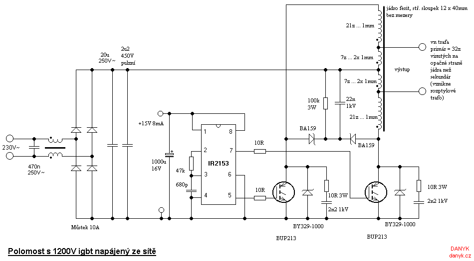
Pushpull inverter with BUP213 IGBT
An IGBT inverter circuit diagram is a detailed schematic of an inverter circuit that uses insulated gate bipolar transistors to convert direct current into alternating current. This type of circuit diagram is a useful tool for understanding how electricity works and can be used to troubleshoot problems with electrical equipment.

IGBT Modules IGBT Inverter Semiconductors Fuji Electric Corp. of America
Simple Inverter Circuit Diagram Using Igbt By Clint Byrd | May 29, 2018 0 Comment The Inverter Circuit is an essential component of renewable energy technology, enabling users to convert DC power from batteries or solar panels into AC power that can be used to power day-to-day home appliances and other devices.

Pin on ELECTRONICS
IGBT combines the low saturation voltage of a transistor with the high input impedance and switching speed of a MOSFET. The outcome obtained from this combination delivers the output switching and conduction characteristics of a bipolar transistor, but the voltage is controlled like a MOSFET.
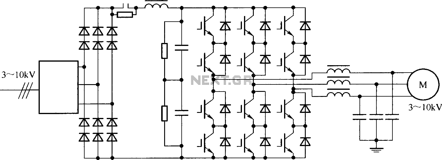
92 3 PHASE INVERTER CIRCUIT DIAGRAM USING IGBT InverterDiagram
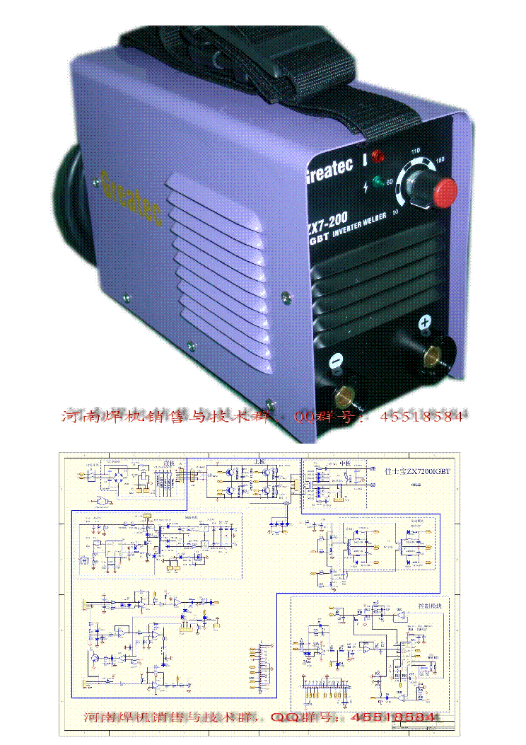
The IGBT inverter welding machine circuit diagram, also known as a schematic, is a visual representation of the electrical components and connections within a welding machine. It typically shows the power supply, transformer, power rectifier, and the output side of the welding machine, including the welding torch and electrodes..
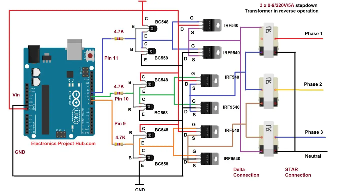
Three Phase Inverter Circuit Diagram DIY Electronics Projects
Step 1: Single-phase Inverter. A power inverter, or inverter, is an electronic device or circuitry that changes direct current (DC) into alternating current (AC). Depending upon the number of phases of the AC output, there are several types of inverters. Single-phase inverters. Three-phase inverters.
Electronics Free FullText Design and Hardware Implementation of an IGBTBased HalfBridge
An IGBT inverter schematic diagram consists of several basic components. The primary component is an IGBT module, which is used to convert AC power from the wall outlet into DC power to be used by the device or system.

Igbt Inverter Circuit Diagram Pdf
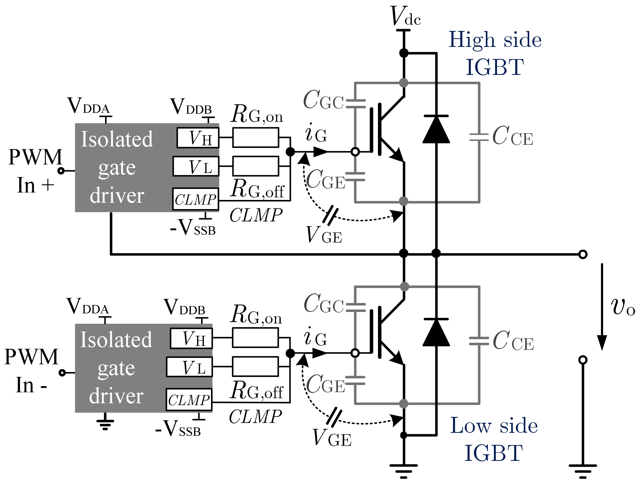
The gate drive circuit comprises of three UCC21520 devices, which are dual IGBT gate drivers. The UCC21520 has many features to design a reliable three phase inverter. The UCC21520 has a built-in dead-time insertion feature, which can insert a dead time into a complementary PWM for a half-bridge even if the PWMs overlap.

igbt How softswitching works in these circuit? Electrical Engineering Stack Exchange
1 General IGBT overview. The insulated-gate bipolar transistors (IGBTs) combine a MOS gate with high-current and low-saturation-voltage capability of bipolar transistors as illustrated in Figure 1, and they are the right choice for high-current and high voltage applications. IGBT and MOSFET operation is very similar.
14+ Igbt Inverter Circuit Diagram Robhosking Diagram
IGBT. If the turn off delay of a large IGBT is perhaps 1500ns at max temperature, with a propagation delay through the galvanically isolated gate drive circuit of 500ns worst case, with a worst case motion control engine interrupt of 2000ns and a current transducer settling time of 1us, the IGBT in the circuit must then be able to withstand
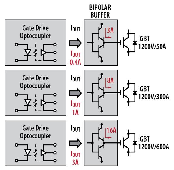
Igbt Gate Driver Circuit Design
In practical applications, IGBT (insulated-gate bipolar transistor) inverters have gradually replaced power FET MOSFETs due to their ability to handle larger on-state currents, higher forward-reverse configuration voltages, and voltage-controlled switching. IGBT s offer distinct advantages, especially in medium to high-voltage capacity systems.

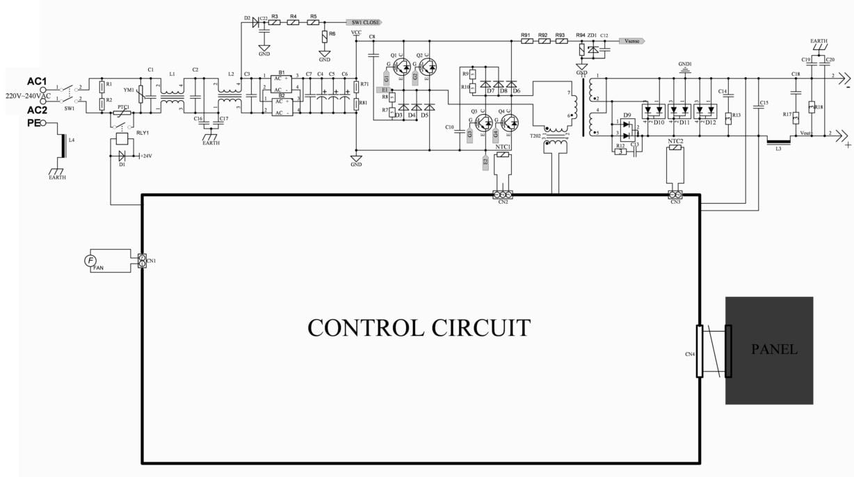
[DIAGRAM] Igbt Welding Machine Schematic Diagram
The circuit diagram of an IGBT inverter welder typically includes the following main components: Rectifier Stage: The rectifier stage consists of diodes that convert the AC input voltage to a DC voltage. This DC voltage provides the necessary power for the subsequent stages of the welder.